|
ELECTRIC WATER HEATER Installing and Operating Instructions
A SPANISH LANGUAGE VERSION OF THESE INSTRUCTIONS IS AVAILABLE BY CONTACTING
THE MANUFACTURER LISTED ON THE RATING PLATE.
LA VERSION ESPANOLA DE ESTAS INSTRUCCIONES SE PUEDE OBTENER AL ESCRIBIRLE
A LA FABRICA CUYO NOMBRE APARECE IN LA PLACA DE ESPECIFICIONES.
THE WARRANTY ON THIS WATER HEATER IS IN EFFECT ONLY WHEN THE HEATER
IS INSTALLED AND OPERATED IN ACCORDANCE WITH LOCAL CODES AND THESE INSTRUCTIONS,
THE MANUFACTURER OF THIS HEATER WILL NOT BE LIABLE FOR ANY DAMAGE RESULTING
FROM FAILURE TO COMPLY WITH THESE INSTRUCTIONS. READ THESE INSTRUCTIONS
THOROUGHLY BEFORE STARTING.
LOCATION:
Select a location accessible to water lines and power supply where the
floor is level. Do not locate the heater where water lines could be subjected
to freezing temperatures. It is recommended that the heater be located
near the center of greatest hot water usage to prevent heat loss through
the pipes. Locate the heater so that access panels and drain valves are
accessible.
THE HEATER MUST BE LOCATED IN AN AREA WHERE LEAKAGE OF THE TANK OR CONNECTIONS
WILL NOT RESULT IN DAMAGE TO THE AREA ADJACENT TO THE HEATER OR TO LOWER
FLOORS OF THE STRUCTURE. WHEN SUCH LOCATIONS CAN'T BE AVOIDED, A SUITABLE
DRAIN PAN MUST BE INSTALLED UNDER THE HEATER. SUCH PAN MUST BE AT LEAST
1 1/2" DEEP, HAVE A MINIMUM LENGTH AND A WIDTH AT LEAST 2" GREATER
THAN THE DIAMETER OF THE HEATER, AND SHOULD BE PIPED TO AN ADEQUATE DRAIN.
WARNING:
Do not use or store gasoline or other flammable vapors, liquids, or
materials in the vicinity of this or any other appliance.
NOTE:
Before proceeding with the installation, close the main water supply
valve, open a water faucet to relieve the house pressure and then close
the faucet.
CAUTION:
DO NOT TURN ON ELECTRICAL CURRENT TO WATER HEATER UNTIL TANK HAS BEEN
COMPLETELY FILLED WITH WATER. OPEN SEVERAL HOT WATER FAUCETS TO ALLOW
AIR TO ESCAPE FROM THE SYSTEM WHILE THE HEATER IS FILLING. THE HEATING
ELEMENTS WILL BURN OUT IF NOT IMMERSED IN WATER.
CAUTION:
FOR YOUR SAFETY BE AWARE THIS WATER HEATER IS CAPABLE OF PRODUCING HOT
WATER AT A TEMPERATURE SUFFICIENT ENOUGH TO CAUSE SCALDING INJURY. READ
INSTRUCTIONS CAREFULLY BEFORE OPERATING THIS UNIT.
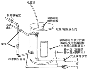
UPRIGHT MODELS: See Figure 1
The hot and cold water connections are identified on the top of the
heater. Connect the hot and cold water lines to the installed nipples
using unions. Install a listed temperature-pressure relieve valve in the
remaining fitting.
ELECTRICAL CONDUIT TEMPERATURE AND PRESSURE RELIEF VALVE
COMBINATION ANODE-HOT WATER OUTLET FITTING UNIONS COLD WATER SUPPLY
SHUT-OFF VALVE (MUST BE OPEN DURING HEATER OPERATION) REMOVABLE PLATE
FOR ACCESS TO WIRING
COMBINATION DIP TUBE-COLD WATER INLET FITTING RELIEF VALVE DISCHARGE
LINE
REMOVABLE ELEMENT COVERS FOR ACCESS TO THERMOSTATS AND HEATING ELEMENTS
WIRING DIAGRAM IS ON BACK OF ELEMENT COVER DRAIN VALVE RELIEF VALVE
DISCHARGE LINE
ALTERNATE TEMPERATURE AND PRESSURE RELIEF VALVE LOCATION
DRAIN PAN (PIPED TO DRAIN AS ILLUSTRATED)
UTILITY MODELS: See Figure 2
The hot and cold water connections are identified on the side of the
heater. Connect the hot and cold water lines to the installed nipples
using unions. Install a listed temperature-pressure relief valve in the
opening on the side of the heater. Install a vacuum relief anti-siphon
device in the cold water inlet line.
ELECTRICAL CONDUIT ANTI-SIPHON DEVICE HOT WATER OUTLET UNIONS
COLD WATER SUPPLY REMOVABLE PLATE FOR ACCESS TO WIRING
TEMPERATURE AND PRESSURE RELIEF VALVE REMOVABLE ELEMENT COVER FOR
ACCESS TO THERMOSTAT AND HEATING ELEMENT (WIRING DIAGRAM ON BACK OF COVER) DRAIN
PAN (PIPED TO DRAIN AS ILLUSTRATE)
RELIEF VALVE DISCHARGE LINE
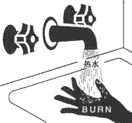
Water temperature over 125oF can cause severe burns instantly
or death from scalds.
Children, disabled and elderly are at highest risk of being scalded.
See instruction manual before setting temperature at water heater.
Feel water before bathing or showering.
Temperature limiting valves are available, see manual.
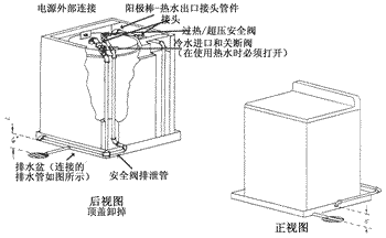
TABLE TOP MODELS: See figure 3
The hot water outlet and cold water inlet are identified on the back
panel of the heater. Remove the porcelain top by sliding it toward and
lifting it off the cabinet. Care should be taken in handling the porcelain
top to prevent chipping of the porcelain. Remove the four front panel
screws; two at the top flange. Check drain valve to make sure that it
is closed. Part the top fiberglass insulation to allow access to the plumbing
and electrical connections. Connect the cold water supply line and hot
water outlet lines using elbows, nipples and unions as shown in the diagrams.
Install a shutoff valve in the cold water inlet. Install a listed temperature-pressure
relief valve in the remaining fitting.
ELECTRICAL OUTLET CONNECTION COMBINATION ANODE-HOT WATER OUTLET FITTING UNIONS
TEMPERATURE AND PRESSURE RELIEF VALVE COLD WATER INLET AND SHUTOFF
(MUST BE OPEN DURING HEATER OPERATION) DRAIN PAN (PIPED TO DRAIN AS
ILLUSTRATED) RELIEF VALVE DISCHARGE LINE
REAR VIEW TOP REMOVED FRONT VIEW
FAILURE TO INSTALL AND MAINTAIN A NEW, LISTED 3/4" X 3/4"
TEMPERATURE-PRESSURE RELIEF VALVE WILL RELEASE THE MANUFACTURER FROM ANY
CLAIM WHICH MIGHT RESULT FROM EXCESSIVE TEMPERATURE AND PRESSURES.
Do not install a check valve or other devices that would prevent reverse
flow of water unless required by local codes. A closed system will result
and frequent operations of the relief valve will occur.
CAUTION:
The reduce the risk of excessive pressures and temperatures in this
water heater, install temperature and pressure protective equipment required
by local codes, but not less than a combination temperature and pressure
relief valve certified by a nationally recognized testing laboratory that
maintains periodic inspection of production of listed equipment or materials,
as meeting the Requirements for Relief Valves and Automatic Gas Shutoff
Devices for Hot Water Supply Systems, ANSI Z21.22, available from the
American Gas Association, 1515 Wilson Blvd., Arlington, VA 22209. This
valve must be marked with a maximum set pressure not to exceed the marke
working pressure on the water heater. This valve must also have an hourly
rated temperature steam BTU discharge capacity not less than the hourly
input rating of the water heater. Install the valve into the opening provided
and marked for this purpose in the water heater, and orient it or provide
piping so that any discharge from the valve will exit only within 6 inches
above, or at any distance below the structural floor and cannot contact
any live electrical part. No valve is to be placed between the relief
valve and tank. The discharge line must be installed to allow complete
drainage of both the relief valve and the discharge line. The discharge
line must not be restricted or reduced in size under any circumstances.
The end of the discharge line opening should terminate near a floor drain
or other suitable location not subject to blocking or freezing. DO NOT
thread, plug or cap the discharge line. Leave an air gap of approximately
six (6) inches between the end of the discharge line and a drain pan.
(see figure 1).
After the installation of all water lines, open the main water supply
valve and fill the heater. Open several hot water faucets to allow air
to escape from the system while the heater if filling. When water passes
through the faucets, close them and check for possible leaks in the system.
ELECTRICAL CONNECTIONS:
Before any electrical connections are made, be sure that the heater
is full of water and that the valve in the cold water supply line is open.
Check the rating plate and wiring diagram before proceeding. This electric
water heater was built and wired in accordance with the Underwriters'
Laboratories' testing approvals requirements. The temperature limiting
device is of the manual reset, trip-free type and has been factory installed
to interrupt all ungrounded power supply conductors in the event of thermostat
failure. Thermostats are factory set and wired in accordance with the
wiring diagram fastened to the inside of the top access panel.
The dealer in your area ordered this heater wired at the factory to
comply with existing area codes, but local utility codes may require or
allow other circuity. Consult your local power company to determine the
correct electrical hook-up in order to meet local utility and building
codes and in order to obtain the most economical rates. Also check to
find out if you are required to obtain a permit before starting the installation.
The following chart shows the recommended fuse size for the maximum heater
wattage. The maximum wattage and rated voltage are shown on the heater
data plate.
The heater must be well grounded. A green ground screw is provided at
the electrical connection point for connecting a ground wire.
OPERATION:
Before closing the switch to allow electric current to flow to the heater,
make certain that the heater is full of water and that the cold water
inlet valve is open. Complete failure of the heating elements will result
if they are not totally immersed in water at all times. When the switch
is closed, the operation of this electric water heater is automatic. The
thermostats are preset to the "HOT" setting to provide a water
temperature of approximately 120oF to reduce the risk of scald
injury. CAUTION: Scalding may occur within five (5) seconds at a temperature
setting of 135oF.
This water heater is capable of delivering high temperature hot water
at any faucet in the system. Care must be taken whenever using hot water
to avoid scalding injury. Certain appliances require high temperature
hot water (such as dishwashers and automatic clothes washers). In order
to prevent potential scald injury, install an antiscald tempering valve
in the water system. Valves for reducing point of discharge temperature
by mixing cold and hot water in branch water lines are available. A qualified
plumber should be consulted.
The temperature of the water can be changed by adjusting the thermostats.
Before any work is done on the heater, disconnect all power to the heater
by opening the switch at the main electrical circuit breaker of fuse box.
Remove the access panels or front panel on table tops, fold the insulation
outward away from the controls. Set the thermostats to the desired water
temperature using a screw driver to move the thermostat pointer, replace
the insulation making sure that the controls are well covered and that
the plastic terminal shield has not been displaced; then replace the access
panel. The heater is now ready for operation and the main switch can be
closed.
For Your Safety: Increasing the wattage and/or voltage from factory
original equipment can require changes to the water heater and/or the
electric service. Unauthorized modification of the water heater may create
a hazard to life and property and will nullify the warranty. Contact your
dealer or utility company before making any changes.
- COMBINATION COLD AND HOT WATER FITTINGS ARE FACTORY INSTALLED FOR
EASE OF INSTALLATION AND ENERGY SAVINGS. DO NOT REMOVE THE INSERTS IN
THE FITTINGS.
- WATER CONNECTIONS IN HEATER ARE 3/4" TAPERED PIPE THREAD.
- THE RELIEF VALVE DISCHARGE LINE SHOULD TERMINATE 6" ABOVE A SUITABLE
OPEN DRAIN.
- IF SWEAT FITTINGS ARE USED, DO NOT APPLY HEAT TO THE NIPPLES ON TOP
OF THE HEATER. SWEAT TUBING TO ADAPTOR BEFORE FITTING ADAPTOR TO WATER
CONNECTION. IT IS IMPERATIVE THAT NO HEAT IS APPLIED TO CONNECTION AS
NIPPLES CONTAIN A PLASTIC LINER.
MANUFACTURED UNDER ONE OR MORE OF THE FOLLOWING U.S. PATENTS: Re. 34,534;
4,416,222; 4,628,184; 4,669,448; 4,672,919; 4,808,356; 4,829,983; 4,861,968;
4,904,428; 5,000,893; 5,000,893; 5,023,031; 5,052,346; 5,092,519; 5,115,767;
5,199,385; 5,277,171; 5,341,770; 5,372,185; 5,485,879; 5,574,822; 5,596,952;
5,660,165; 5,682,666; 5,943,984; 5,954,492. OTHER U.S. AND FOREIGN PATENT
APPLICATIONS PENDING. CURRENT CANADIAN PATENTS: 1,272,914; 1,280,043;
1,289,832; 2,112,515.
CAUTION: INCREASING THE THERMOSTAT SETTING ABOVE THE PRESET TEMPERATURE
MAY CAUSE SEVERE BURNS AND CONSUME EXCESSIVE ENERGY. HOTTER WATER INCREASES
THE RISK OF SCALD INJURY.
When necessary to completely drain the heater, shut to off the electric
power supply to heater, close cold water inlet, open a hot water faucet
to allow air to enter the system and open the drain valve, which is threaded
to receive a standard hose coupling. On Table Top models, the front panel
must be removed to gain access to the drain valve.
CAUTION: Hydrogen gas can be produced in a hot water system served
by this heater that has not been used for a long period of time (generally
two weeks or more.) Hydrogen gas is extremely flammable. To reduce the
risk of injury under these conditions, it is recommended that the hot
water faucet be opened for several minutes at the kitchen sink before
using any electrical appliance connected to the hot water system. If hydrogen
is present, there will probably be an unusual sound such as air escaping
through the pipe as the water begins to flow. There should be no smoking
or open flame near the faucet at the time it is open.
MAINTENANCE:
Shut off the electric power whenever the water supply is turned off.
Shut off the electric power, water supply and drain the heater completely
to prevent freezing whenever the building is left unoccupied during the
cold weather months. In order to insure efficient operation and long tank
life, drain the heater through the drain valve until water runs clear.
Drain it at least once a month. Failure to do this may result in noisy
operation and lime and sediment buildup in the bottom of the tank. Check
the temperature-pressure relief valve to insure that the valve has not
become incrusted with lime. Lift the lever at the top of the valve several
times until valve seats properly without leaking and operates freely.
SAFETY WARNING: When lifting lever of temperature/pressure relief valve,
hot water will be released under pressure. Be certain that any released
water does not result in bodily injury or property damage. The magnesium
anode rod should be inspected periodically and replaced when necessary
to prolong tank life.
SERVICE:
The manual reset, trip-free temperature limiting devices on this heater
will cut off all power to heater if temperature of water exceeds 190oF.
If there is no hot water after a reasonable period of time, check the
main fuse box. In the event that the fuses have not blown, call a serviceman;
have him check the entire circuit including the elements and thermostats
before resetting the temperature limiting device. Heater must be disconnected
from power supply before servicing switch. Consult the plumber or electric
service company in your area for all service, replacement parts or any
questions you might have regarding this heater. Insist on factory inspected
and approved replacement parts.
A combination anode rod/hot water outlet nipple has been installed to
extend tank life. This rod should be inspected periodically and replaced
when necessary. Contact manufacturer listed on rating plate for replacement
anode information. The use of a water softener may increase the speed
of anode consumption. More frequent inspection of the anode is needed
when using softened (or phosphate treated) water.
Magnesium anode is used to extend tank life. Removal of this anode for
any purpose will NULLIFY THE WARRANTY.
Read the warranty attached to this water heater for a full explanation
of the time period that parts and heater are warranted.
|