

Electrical Characteristics
Model B-710,115V AC, 15 Amp, 1725 Watts, 60 HZ, Single Phase, cULus listed.
Model B-710E, 220-240V, 7A, AC 1500-1700 Watts, 50/60 Hz, Single Phase; VDE approved, CE marked. B-710E is not available in the United States and Canada.
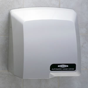
Installation instructions and template provide information that will assist in the installation of the Bobrick B-710 115V, B-710E 220-240V. Retain Installation Instruction Sheet for important maintenance instructions and warranty information.
Recommended Mounting Heights
Distance from floor to bottom mounting screw holes of mounting base. Men's
Washrooms....................................................................................................................................................................................................46" (1170mm)
Women's Washrooms....................................................................................................................................................................................44" (1120mm)
Children's Washrooms, ages 3-9...................................................................................................................................................................32" (815mm)
Children's Washrooms, ages 9-12.................................................................................................................................................................36" (915mm)
Children's Washrooms, ages 12-15...............................................................................................................................................................40" (1015mm)
Children's Washrooms, ages 15-18...............................................................................................................................................................44" (1120mm)
Barrier-Free Design.......................................................................................................................................................................................38" (965mm)
* Bobrick automatic hand dryers should be installed 15" (380mm) above any projection or horizontal surface which may interfere with the operation of the automatic sensor.
Important
* Warm air hand dryer. Intended for use in a household environment by non-expert users. Not suitable for outdoor use.
** This appliance can be used by children aged from 8 years and above and persons with reduced physical, sensory or mental capabilities or lack of experience and knowledge if they have been given supervision or instruction concerning use of the appliance in a safe way and understand the hazards involved. Children shall not play with the appliance. Cleaning and user maintenance shall not be made by children without supervision.
*** If a fault develops disconnect the electrical supply, a qualified electrician should be called.
Removal of Cover
- Start installation of dryer by removing cover. Remove three screws, one from each side and one from the bottom of the dryer. Lift the cover from the mounting base.

Installation of Mounting Base
FOR PROPER ELECTRICAL CONECTIONS, CHECK LOCAL BUILDING CODE. UNIT MUST BE INSTA LLED BY A QUA LIFIED LICENSED ELECTRICIAN
- Hold the Installation Template against the wall in the desired location of the installed dryer, see recommended mounting heights above.
- Make sure line on template representing bottom of dryer mounting base is horizontal and located at the desired height above floor.
- Mark center of four mounting screw holes and hole for entry of electrical wiring if electrical supply is concealed in wall and will enter dryer from back through mounting base.
NOTE: Surface-mounted electrical supply entry is located in the lower right corner of the mounting base. Bottom of mounting base has 1/2" square (13mm) opening in lower right corner to accommodate connection of electrical conduit.
- Drill four holes for #10 (M4.8) mounting bolts or screws (not furnished).
- For masonry walls provide four #10 expansion shields or anchors and secure with four #10 (M4.8) sheet-metal screws (not furnished). For plaster or dry wall construction, provide concealed backing to comply with local building codes and secure with four #10 (M4.8) round-head sheet-metal screws, or 3/16" (5mm) toggle bolts (not furnished).
NOTE: Use 2" (50mm) long screws in top two mounting holes. Use 3" (75mm) long screws in lower two mounting holes.
- Fasten mounting base securely to wall.

WARNING: TURN ELECTRICAL POWER SUPLY OF
BEFORE MAKING ELECTRICAL CONECTIONS.
DRYER MUST BE GROUN DED (EARTHE D).